How to Select a Servo Press? — A Complete Checklist Covering Load, Accuracy and Machine Configurations
Preface
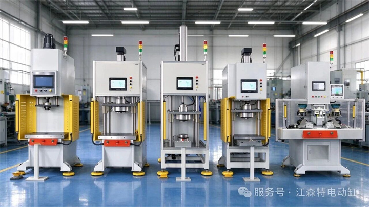
In non‑standard automation and mass‑assembly production lines, servo presses adopt servo‑motor‑driven ball‑screw transmission. Featuring controllable output force and position, traceable process curves, low energy consumption and low noise, they are gradually replacing traditional hydraulic presses and pneumatic presses. They are widely deployed in production lines with high consistency requirements, such as automotive component manufacturing, electronics production and medical‑device fabrication.
Nevertheless, improper selection in real‑world projects frequently leads to insufficient thrust, unsatisfactory press‑fit accuracy, mismatched cycle time with production lines, and even unfeasible processes after equipment delivery, resulting in extremely high rework costs. Most problems stem not from poor equipment quality itself, but from failure to translate actual working conditions into technical parameters during selection.
Drawing on JST’s R&D and application experience, this article systematically explains the logic for servo‑press selection across five major sections.
Force and Stroke
01 Load
Key Consideration
Load is the primary parameter for selection. Perform calculation first before specification selection; avoid specifying tonnage without prior evaluation.
Selection Basis
The press‑fit load shall not directly adopt the theoretical deformation force of the workpiece. Actual working conditions require superposition of material deformation resistance, guiding friction and die resistance. Uncertain factors including burr fluctuation and minor eccentric load shall also be taken into account. Therefore, a safety factor of **1.3‑1.5** is commonly adopted in engineering practice.
Load directly determines ball‑screw specifications and frame rigidity, serving as the decisive input for the overall machine’s load‑bearing capacity.
Selection Recommendation
Submit the target press‑fit force (theoretical press‑fit force multiplied by safety factor) to the manufacturer, rather than only the theoretical workpiece force. Keep the target press‑fit force within **10%‑90%** of the equipment’s full‑scale range, to prevent fatigue of ball screws and frames caused by long‑term full‑load operation.
Example: Where the theoretical press‑fit force for a bearing sleeve is 20 kN, a 30 kN‑grade model is recommended after considering burrs and eccentric load.
02 Speed
Key Consideration
Lower speed brings higher accuracy yet longer cycle time; balance performance according to target takt‑time requirements.
Selection Basis
The working cycle of a servo press generally consists of five phases: rapid advance, probing, press‑fitting, pressure holding and return. Lower speed delivers higher resolution for position control, but extends cycle time accordingly. Engineering trade‑offs shall be made between the two aspects.
Selection Recommendation
Derive speed requirements from target cycle‑time; clearly specify speed and stroke requirements for each phase for manufacturers. Avoid selection merely based on maximum rapid‑advance speed.
03 Stroke
Key Consideration
Stroke shall simultaneously cover material‑feeding clearance, press‑fit depth, die height and safety allowance.
Selection Basis
Insufficient estimation for any dimension will cause failure in normal loading and unloading even when the ram reaches its working position.
Selection Recommendation
Determine stroke by adding **10%‑20%** extra allowance to press‑fit depth, and reserve 20‑50 mm for opening height. Prefer an ample stroke over tight specification, to prevent operational constraints from marginal sizing.
Accuracy and Closed‑loop Control
04 Displacement Accuracy
Key Consideration
Displacement accuracy reflects only whether the ram can repeatedly reach the identical position, commonly at the level of ±0.01 mm.
Selection Basis
Displacement accuracy denotes the ram’s repeat positioning capability. As a basic control indicator for servo presses, it only reflects position consistency and does not directly represent press‑fit quality.
Selection Recommendation
Use displacement accuracy for preliminary screening for precision press‑fitting, yet verify it together with press‑fit accuracy and closed‑loop mode. Do not rely solely on displacement indicators.
05 Press‑fit Accuracy
Key Consideration
Displacement accuracy is not equivalent to press‑fit accuracy. Closed‑loop modes must be clarified for precision press‑fitting.
Selection Basis
Press‑fit accuracy is a comprehensive outcome affected jointly by force closed‑loop control, frame deformation and workpiece consistency.
Displacement‑only closed‑loop constrains position alone. Force‑displacement dual closed‑loop constrains **both position and output force**, which is more favorable for soft and elastic workpieces and avoids crushing caused by position‑only press‑fitting.
Selection Recommendation
For precision press‑fitting applications (bearings, bushings, etc.), prioritize confirmation on adoption of force‑displacement dual closed‑loop control. For production lines requiring quality traceability, request real‑time acquisition of force‑displacement curves and on‑line NG judgment, with a typical curve sampling rate of 1000 samples per second.
Pressure‑holding Process
06 Pressure Holding
Key Consideration
Confirm whether pressure‑holding is required for your process; do not assume this function is available by default.
Selection Basis
Processes such as thermosetting forming, bonding and elastic‑component press‑in normally require pressure‑holding. No pressure‑holding function is needed for other processes.
Selection Recommendation
Confirm three items before placing orders: whether pressure‑holding is needed, pressure‑holding duration, and permissible force fluctuation during pressure‑holding. Retrofitting pressure‑holding after delivery incurs high costs without prior confirmation.
07 Pressure‑holding Duration & Force Fluctuation
Key Consideration
Pressure‑holding duration and permissible force fluctuation directly influence control‑system configuration and overall‑machine costs.
Selection Basis
Pressure‑holding time ranges from several seconds to dozens of seconds. Longer duration and stricter limits for force fluctuation impose higher requirements on servo drives and force closed‑loop control, resulting in higher costs.
Selection Recommendation
Define pressure‑holding duration and permissible force fluctuation according to actual process needs, avoiding extra costs for unused specifications.
System Integration
08 Control & Communication
Key Consideration
Control‑system architectures differ for standalone machines and integrated production lines. Clarify equipment positioning prior to selection.
Selection Basis
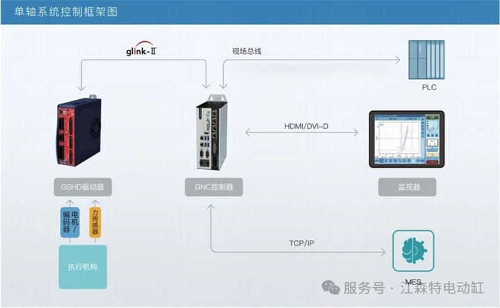
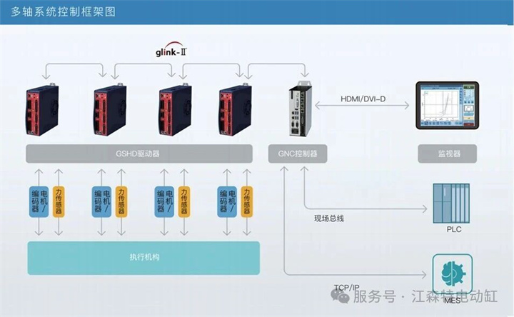
Stand‑alone applications can be satisfied by parameter setting via HMI. For line integration, bus communication with PLCs and loading/unloading robots shall be implemented. Connection to MES may be required for data archiving and traceability.
Once the control architecture is finalized, later modification involves adjustments to both hardware and software, with substantial costs.
单轴系统控制框架图
多轴系统控制框架图
Selection Recommendation
Confirm three items before placing orders: whether pressure‑holding is needed, pressure‑holding duration, and permissible force fluctuation during pressure‑holding. Retrofitting pressure‑holding after delivery incurs high costs without prior confirmation.
Machine Structure & Work Platform
09 Machine‑frame Configuration
Key Consideration
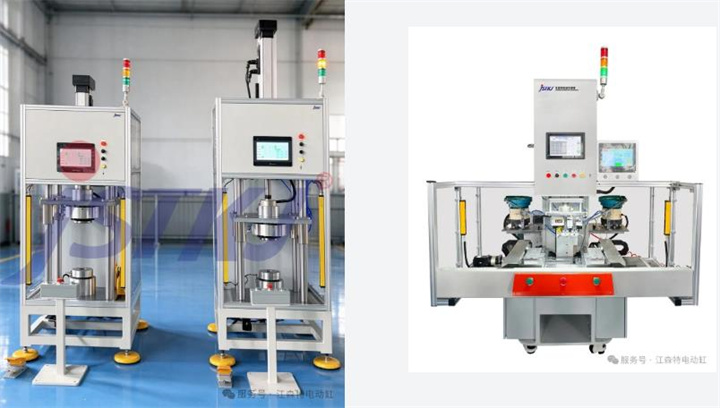
Adopt three‑plate four‑post structure for high‑priority‑accuracy scenarios; select two‑plate four‑post structure for large‑size workpieces and long‑stroke applications.
Selection Basis
The three‑plate four‑post structure delivers high guiding accuracy of the middle plate and strong anti‑eccentric‑load performance, conducive to press‑fit coaxiality. The two‑plate four‑post structure features simple construction, large opening dimension and lower cost, yet relatively relaxed guiding accuracy.
Selection Recommendation
Choose three‑plate four‑post frames for precision press‑fitting and high‑coaxiality‑requirement conditions. Select two‑plate four‑post frames for long‑stroke, large‑workpiece applications with moderate accuracy requirements.
10 Platform Dimensions
Key Consideration
Platform dimensions govern die layout and eccentric‑load stress conditions. Do not select equipment merely based on tonnage rating.
Selection Basis
Press‑fit dimensions of upper and lower platforms determine die layout modes, workpiece locating references and platform stress under eccentric press‑fitting. Press‑fitting workpieces offset to the edge of a large platform will generate eccentric loads on guide posts and ball screws. Long‑term eccentric‑load operation leads to uneven wear of guiding pairs and accuracy degradation.
Selection Recommendation
Determine platform dimensions according to die layout and maximum outer contour of workpieces, and avoid long‑term eccentric press‑fitting. Evaluate the eccentric‑load resistance capacity of guide posts and ball screws for offset press‑fit conditions.
Conclusion
Overall, servo‑press selection is more than simple parameter matching; it represents comprehensive evaluation of press‑fit system performance, process adaptability and long‑term stability.
As industrial automation continuously advances toward higher precision and higher efficiency, servo presses are progressively replacing traditional hydraulic and pneumatic presses. Proper equipment selection together with reliable products guarantees press‑fit accuracy and takt‑time performance while achieving favorable total‑life‑cycle costs.
With twelve‑year‑long industry expertise, JST is headquartered in Taicang, Jiangsu Province, operating a 5,000 m² manufacturing base. Core components are self‑developed and in‑house manufactured. The product portfolio covers servo electric cylinders, multi‑DOF motion platforms, precision positioning slides and servo presses. Custom non‑standard development is supported, delivering customized selection and integration solutions tailored for specific press‑fit conditions.